Thursday, 18 December 2014

Seeing Blue - an unexpected outbreak of mould?

Having written a few lines about why things are seen in my last post, I have been hoisted on my own petard by the recent discovery of a strange change in colour of some parts of one building on Philip's Creek that I have only just noticed.

A few days ago, I was stringing wire to a few fences ( actually the elasticised cotton thread) in close proximity to the Philips Creek Primary School when I saw that parts of the chimney and fascia were now a blue grey colour. We have had some unsettled weather in Sydney over the past few weeks and for 10 weeks prior to that, I was away, so I'm not really sure when the problem emerged. I do know that it wasn't there is 2011 and the third photo demonstrates. However, we have had periods of high humidity in other years without this type of problem emerging so I not sure that weather has been a determining factor.

The other curious thing about this occurrence is that it has not spread across the whole model. The two faces of the chimney and fascia that are not visible to the camera in the first photo remain unaffected. You can get an indication from one of the faces of the chimney in photo 2. There has probably been a reaction with the paint or the weathering powder used, but again, these covered the entire building, and yet, only two sides have been affected. Similarly, as far as I can tell, no other building or rolling stock items has shown signs of contamination.

Well, what to do about it? I tried three methods of removal, each applied with a cotton bud. The results of the first, isocol alcohol, can be seen on the top of the chimney in the first photo. The second, cloudy ammonia, and the third, exit mould, gave similar outcomes, not surprisingly, a bleached white surface.

The visible mould has now been removed and I will repaint fascia once I am convinced that the problem will not return. However, I have decided to build another chimney around the original one. It will be painted and weathered before installation. Hopefully, that will see a return the original structure shown in the 2011 photo.


On a very different note, as the festive season approaches rapidly, I would like to acknowledge all those readers who have assisted me with comments, advice, information or materials associated with the various posts in 2014.  Thank  you all for your contributions and input.

Finally, to all readers, have a very Merry Christmas and a great 2015.


Sunday, 23 November 2014

Why Things Are Seen


This post was started a few months ago after a discussion at the Modelling the Railways of NSW Convention last June but for one reason or another has remained in a half finished state for several months, kind of like a few models I could mention! One of the Sydney Model Railway Society team operating the Society's Mungo Scotts layout bought a 48 class locomotive that he had purchased second hand to the weathering display at the same time that I happened along. The locomotive has some basic weathering but for some reason, a small section had flaked off leaving a triangular shape of the original unweathered surface. Although only small, it was glaringly obvious and he was seeking suggestions of how to repair this.

I had to attend another presentation and I trust he was able to find a solution. However, as we were discussing possible rectification options with the person manning the display, it occurred to me that the issues that we were addressing were the same as those I recall from my early days in the army when one of the first lessons we received was entitled ‘Why Things are Seen’. Back then, the intent was to ensure that our camouflage and concealment practices addressed a number of factors and hence our bodies and equipment were not visible to an enemy. If I recall those factors correctly, they were:
  • shape,
  • colour,
  • silhouette,
  • movement,
  • spacing,
  • shadow,
  • texture, and
  • shine or lustre.
For modellers, the situation is somewhat different. Some things we want to be seen and we usually use one or more of these characteristics to ensure that, but others we wish to remain hidden or at least be less obvious than other elements. 

For many readers of this post, such things are self evident, so why waste time restating the obvious? A few reasons come to mind. Firstly, sometimes it helps to review the concepts that underpin the visual aspects of the hobby. Secondly, it may give some readers a different perspective when it comes to weathering and scenery. Finally, in the perennial question concerning how much detail is appropriate for HO scale, I tend to look at the issue in the context of these factors because my belief is that if you can’t see the detail readily, then perhaps it is not necessary.

In the modelling context, a number of the factors are readily apparent. We spend a lot of time and effort to ensure that the shape and colour are right. Silhouette could be considered as a sub element of shape. In the military context, the silhouette against the skyline is something to be avoided. In the modelling context, it may work to enhance a realistic scene.

In the same way, movement and spacing are also easily appreciated but again, context is important.

However, it is perhaps the last three that present me with the greatest challenges. 

A misplaced shadow can easily compromise a scene and is something that I must address in several parts of Philip’s Creek but more of that in a moment.

We seem to have a sensitivity to texture and I confess that more than once, I have been tempted to reach out and touch a corrugated iron roof on an exhibition layout to see if it feels right. Recent blog posts by others dealing with topics such as brick or block work, or the depth of timber grain on cattle or sheep wagons are, in part, about getting the texture right.

I think the incorrect lustre of a model is one of those things that can really detracts. It was the juxta-positioning of the two lustres, the shiny ‘as purchased’ finish and the dull weathered surface, on the 48 class in the opening vignette that made the problem very obvious. By way of further example, the photo opposite shows a situation where the incorrect lustre makes something look out of place. We expect the top of the tracks to reflect some light but the new, and as yet unweathered, flat wagon tends to catch the eye and possibly distract the viewer. Not all gloss or shine is a problem, but if we get wrong, either way, it stands out. 


The second photo attempts to highlight a few examples of these factors at work. The effect of shape, colour and shadow is fairly obvious in defining the scene, but the shape of the masking tape on the track certainly ensures that it is visible even though the colour is not terribly out of place. Perhaps less obvious in the photo, but apparent when viewed in person, is the impact of texture and shine. The pond in the foreground was created using several coats of clear gloss vanish over a darkened ground. The colour and lustre is about right but the roughened texture of the ground gives the  appearance of running water rather than a still stagnant pond that was intended - a bit more work to do there.

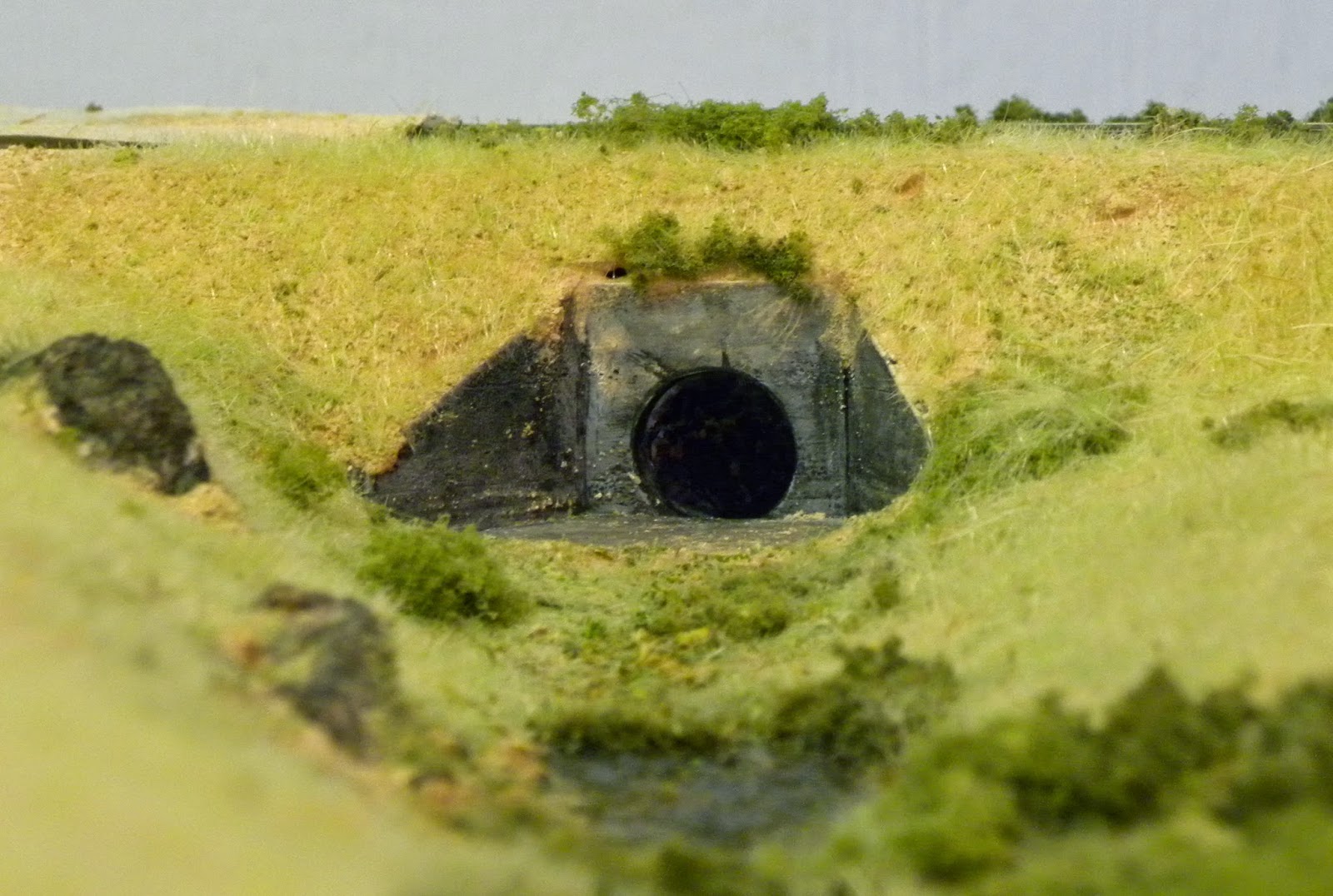
The shadow of the culvert entrance is expected but the astute observer will also note the small unwanted shadow at the top left of the headwall. This void is where the terrain and the headwall do not quite match. This an example of something that we don't want seen and normally theses are covered by vegetation, but clearly I missed one. Sometimes the camera sees better than the eyeball.

Finally, to return the shadow. Ron Cunningham in his Branchline Ramblings segment in AMRM (October 2014) wrote about a trend in model railway design towards the use of narrow shelves as a part of the layout. The photo opposite shows a  potential consequence of that trend as the shadow of a passing train may fall on the backdrop betraying the proximity of the backdrop which otherwise would visually appear to be more distant. I need to investigate this further as it's an issue I have in several locations. I suspect that some form of lighting immediately above the backdrop may be the best solution for this.
As I said at the start, most modellers understand these factors implicitly and use them successfully. However, for me and perhaps others, occasionally, something slips through the cracks and it helps to recap the basics.


Tuesday, 11 November 2014

A 36ft Tank Wagon aka Grandfather's Axe


When I converted back to HO scale in 1996, the first wagon that I purchased was an Athearn  US three dome tank wagon. The primary purpose of this acquisition was to test the new track that was being laid. In my ignorance at the time, I also thought that it could provide a 'near enough' version of its NSW equivalent. Although, I was soon set straight on this point, the wagon continued to operate as the only tank wagon on Philip's Creek. Fast forward to last December and the arrival of my SDS tank wagons. The old Athearn wagon now looked very out of place and languished in the 'back of house' staging area.

A few months later, Peter Hearsum posted retrospective on some 9000 gallon tank wagons that he had built quite a few years ago ( http://burrowa.wordpress.com/2014/05/21/a-lesson-learned/). Peter had co-authored an article on this work in an issue of the magazine Branchline Modeller (later The Australian Journal of Railway Modelling). Fortunately, I had a copy of the issue, reread it, and noted that one of the two wagon used as the start point for the conversion was the Athearn three dome tank wagon. I contacted Peter and he very kindly helped me out with the specialist dome and end casting, and cylinder to complete the conversion. Many thanks Peter!

I followed the process outlined in the article fairly closely but stuffed up the shortening of the chassis. To overcome this, I glued a styrene channel section on each side of the centre bream to create a sandwich arrangement which allowed me to achieve the straight line that my earlier attempts had not achieved.

I did get a bit confused with the different arrangements of domes, ladders, handbrakes and securing straps. As a consequence, I decided to follow the drawing of the Caltex 9000 gallon tank wagon on page 8 of the magazine. The model now just requires painting and the procurement of some suitable Caltex decals before returning to service.

The one thing the article did say at the very start was that most of the Athearn kit should be discarded and this was certainly the case. I have chosen to show photos before painting to demonstrate this point. The dark grey coloured parts of the model (not to be confused with the new grey domes and tank ends) are the only components from the original wagon hence the reference to grandfather's axe. We are all familiar with the story of grandfather's axe. It had seven different handles and five new heads but it was still grandfather's axe. And so it is with the tank wagon, although heavily modified it is still the first wagon that ran on Philip's Creek


Friday, 31 October 2014

A Narrow Gauge Deviation


Towards the end of our visit to Northern America, my wife and I visited the delightful town of Durango in Colorado. Delightful not only because of its location but also because it is the home of the Durango and Silverton Narrow Gauge Railroad. There are many heritage and tourist railroads in the US and we have encountered a few of these during our vacation. While it’s a bit tenuous, the attraction of this particular railroad is that it operates on part of the old Denver and Rio Grande Railroad running on a 3ft gauge track, the same gauge that I have modelled on my short logging railway operating out of Mount Windeatt

Our itinerary did not permit a trip on the train but it did allow us to witness the arrival of the last tourist train for 2014. Operating steam at last! Durango, as the terminus, has an extensive yard with a collection of rolling stock predominately carriages. It also includes an interesting museum. The museum is not big, occupying about three or four stalls of the old roundhouse. Its collection is more extensive than the usual railway memorabilia, including vintage cars and motor bikes, replica aircraft, a model railway and a collection of military figurines. Entrance to the museum was free. 
 
The museum was also pushing a range of local HOn3 models marketed under the Blackstone Models label (http://blackstonemodels.com/). As is common with most models these days, they are manufactured in China to the same standards we now expect from ready to run models. They are not cheap but very nicely detailed and well, the inevitable happened! I weakened and purchased a flat car similar to the one shown below.

It was a great visit to Durango!
The question now is what to do with this new acquisition. I already have a few logging cars in service and the very short sidings at Mount Windeatt discourage longer consists. The options are to use it to carry equipment in a similar way to the wagon photographed at the Durango roundhouse. Alternatively, I could build or modify a carriage section to fit over half of the wagon. Then, it could be used to provide basic passenger transport moving loggers between the sawmill and the logging site. I seem to recall seeing something similar in a narrow gauge magazine that I purchased many years ago. I’ll have to wait a few days until my return to Australia to confirm this. 

However, I don’t anticipate that work on this wagon will happen at any time in the short term after our return. There will be too many other things to catch up not to mention cleaning up Philip’s Creek after an absence of nearly three months. Hopefully, a possum hasn’t taken up residence but I’m certain the geckos will have left a few calling cards.  

Saturday, 13 September 2014

A Change of Scale and Prototype


This post is a bit 'off topic' but no, I'm not moving away from the NSWGR prototype or away from HO scale.

Currently, my wife and I are on our first major retirement trip to catch up with friends in the US and Canada as well as visiting some places that we haven't seen in our earlier sojourns to this part of the world. So I thought I would post a few images of two of the 1:1 scale US railroads we have encountered to date.

The first three photos come from the White Pass and Yukon Railroad in Alaska. The narrow gauge railroad was originally built to provide a link to the Alaskan gold fields in the late 1890s. The 110 miles of track was constructed in a very fast two and a half years just in time for gold rush to falter and then subside. However, the railroad continued to operate commercially until the early 1980s when it closed, only to reopen as a tourist railroad in 1988.


The railroad currently operates a mixed diesel fleet of GE locomotives from the 1950s and Alcos from the 1960s hauling a number of restored passenger coaches. Their literature also states that they run two restored  Baldwin steam locomotives but these were not present when we visited. All I saw was this old Mikado looking like it has seen better days and is probably providing spares for the operational locomotives.


However, what sets the WP&YRR apart is its engineering in a very harsh environment. The track hangs on the side of a substantial valley with grades up to 3.9%, numerous bridges and a few tunnels.  Perhaps the most dramatic bridge encountered, in the 40 mile round trip that we did, is the one shown in the photo. It is no longer in use with the trestles and probably the steelwork in very poor condition. However, I suspect that it remained operational until the 1990s at least. What sets it apart, in my view, is the apparent lightness of the steel structure. It's a great example of the versatility of the steel truss design.

The second group of three photos covers two competing railroad companies running parallel operations on banks of the Columbia River Gorge that forms part of the border between Washington and Oregon states. The operations of the BNSF Railway and its rival, the Union Pacific Railroad seem fairly typical, multiple units pulling very long freight trains frequently with additional assistance at the rear as this photo shows. However, what sets this area apart is the spectacular setting with railways operating on either side of a very wide river dominated by massive basalt cliffs and steep slopes.

If one were to attempt to model accurately the mountains dominating the Columbia River in this area in HO scale, the mountains  would need to be somewhere between 10 and 30 feet high with the odd peak rising higher still. That's a lot of Styrofoam! The photo opposite, taken just west of the township of Hood River in Oregon, actually shows a BNSF train moving on the northern bank of the river. It appears only as a thin multi-coloured line just above the water line.


The final photo shows the same train, this time with a 24x zoom (the best I can get out of my camera) looking like a distant photo of someone's N scale layout.

I once wrote about the concept of 'modelling the ordinary' but on the Columbia River, the 'ordinary' is spectacular.

Next stop is the Rocky Mountains in Canada.


Obviously, physical work on Philip's Creek has been temporarily suspended while we are away. However, a copy of XTrackCAD loaded on the laptop has allowed me to work on the plan for the upper level of the layout. This may be getting ahead of myself as I haven't yet finished the Halls Creek Bridge scenery or started the transition and helix that will enable an upper level, but hey, there's nothing like thinking ahead!


Friday, 8 August 2014

The Hall's Creek Bridge 3 - Still a work in progress


My last two posts have focused on the construction of a simple bridge based on the Hall’s Creek bridge on the abandoned section of the Merriwa Branch line. I am now at a point where the bridge structure must be ‘planted’ on the layout so the final landscaping can be integrated with the overall landscaping of the module.

I fashioned the bridge abutments from  stripwood and the other retaining walls from Wills timber planking. The check rails were fabricated from a length of Code 75 track, glued to the sleepers, and then painted with Rail Brown (part of my dwindling stock Floquil paints).

My activities are now concentrating on the construction of the surrounding landscape and laying the track leading to the bridge. Once the adjoining track height has been established, the position and height of the bridge will be adjusted to ensure the correct alignment. With the bridge finally located, the surrounding terrain including the actual water course can be shaped and sceniced. 

I am reasonably happy with the outcome, but as always, there is room for improvement. As a whole, the bridge looks OK, although some individual components are below par if subjected to close scrutiny. Perhaps the most disappointing elements are the concrete columns. After several attempts, I couldn't replicate the impression of the timber formwork planking that can be seen on the prototype. I probably should have cast something in plaster, but if it bugs me too much, I can install these retrospectively.
Photo from "NSW Steam Train Ride To Merriwa - John Gaydon  (http://steamtrainstories.com/category/australia/nsw/)

I could spend more time tweaking the detail but I need to keep moving towards the helix and upper deck construction, otherwise the bridge will become a "bridge to nowhere" and end up like its prototype.


Friday, 18 July 2014

The Halls Creek Bridge 2 - A Thank You

Following my earlier post on the topic, Ian Phemister  (http://iansmuswellbrookmerriwa.blogspot.com.au/) kindly provided me with a copy of his photos on the same subject taken from his extensive collection of information on the Merriwa line. It is a goldmine of detail. The first thing I noticed was that the shorter of the timber pier sets only has three piers rather than the four that I had constructed (based on old standard drawings). This has now been corrected. 

From Ian's information, it is also interesting to note that an extra pier set has been added to reduce the span between the larger timber pier set and the abutment. I presume this occurred sometime after 1970 as it certainly not there in a 1970 photo of 3090 taken on the bridge.

Many thanks Ian. Your assistance is greatly appreciated.

To start the fabrication of the components, I fixed a length of track upside down to a strip of ply and then glued the steel and timber beams to the underside of the track. The main concrete piers were shaped from styrofoam, coated a mix of coloured tile grout and 50/50 PVA/water, and weathered further with soft pastels and isocol alcohol. Looking at the photo below, I may need to revisit the right hand pier to lighten it up somewhat.

The concrete piers were then glued to underside of the steel beams, and then a further strip of ply was glued to the underside of the piers thus creating a plywood sandwich. Additional styrofoam was added to create the locations for the abutments and timber pier sets. Again, looking at the photo (still a work in progress), a bit of shimming is still required to remove the slight curvature that can be seen around both bridge abutments.


Once the basic alignment has been finalised, the terrain will be finalised, and then I can focus on the detail of the abutments and the underside of the bridge using the information Ian provided.

Monday, 14 July 2014

The Halls Creek Bridge

Photo from Merriwa Rail Society website - Photographer Unknown
After removing the non-prototypical and very distinctive brick viaduct, I still would like to have at least one reasonably sized bridge on the layout. Over the last few months, I have been searching the internet for possible prototypes and came across the bridge over Halls Creek at Sandy Hollow on the now disused Merriwa branch line. Interestingly, Google Maps (a very definitive source??) names the watercourse at the crossing point as Giants Creek but all of the literature that I have found refer to it as Halls Creek.

Photo from Merriwa Rail Society website - Photographer Brian Leedham
According to the Byways of Steam article on the Merriwa line (Byways of Steam 10 p62), this bridge was one of three on the branch line and the only one no longer in service. It is also the most basic but perhaps, the most interesting of the three with a combination of steel and timber superstructure and a mixed arrangement of piers. The other great attraction for this bridge is that a gentleman by the name of Brian Leedham took some photos of the main span which was still in place in 2009 and these have also been published in the Merriwa Railway Society's website (http://www.merriwarailwaysocietyinc.org/alongtheline.htm). The photos have been a great help in determining the arrangement of the main beams and the internal bracing for these. They also give an idea of the arrangement of the timber bearers on the shorter spans.

My intent is not to create an exact copy but use the bridge as a guide. Unfortunately I have not been able to locate any drawings for the bridge, and therefore, the dimensions that I am using to create the model are approximate based on comparisons with locomotives and rolling stock shown in several older photos of the bridge.

To date, I have fabricated the major span steel bream arrangement from styrene and the timber piles from bamboo satay sticks and stripwood from Northeastern Lumber. I have also added bolt heads from Tichy Train Products on the timber pier sets but drew the line at adding rivet heads to plate web girders. I have also cheated a little by not including all of the internal vertical cross bracing and the horizontal cross bracing attached to the bottom flange.


Once the individual components bridge are painted, I'll probably finish the bridge upside down, fixing everything to a length of track before placing it in position. 

The bridge when completed will not form part of the main layout but will be shown as a cameo scene on the branch line before it enters a helix that will provide access to the upper level.

More to follow as the project develops.


Sunday, 22 June 2014

Running Tender First - A Basic Kadee Adaptor

A few weeks ago, I identified a scenario where I should operate a train pulled by 5248 running tender first. The only problem was there was no compatible coupler on the front of the locomotive. Having just repainted the model I did not want to fit a Kadee coupler, so I experimented with an adapter that could link the coupler on the rolling stock with the existing hook coupler on the locomotive. I'm sure this has been done before, but my searching on the internet didn't bring up any suggestions. So it was back to first principles and this post details the outcome of that experimentation.

By way of background, about a year ago, I came across a number of Youtube movies showing steam operations on the NSW railways in the 1960s. One of these showing operations in northern NSW is at  https://www.youtube.com/watch?v=HDVUsaeFKhs&feature=relmfu . While the quality of these videos is well below the standard of current cinematography , they are a great source of contemporary information on the topic.

Recently, in search of information on MHO guards vans, I revisited this video and was surprised by the number of empty coal trains (primarily LCH and CCH wagons) being hauled by a standard goods locomotive running tender first. So the hunt was on to find a way to replicate this.

After a couple of tries, I managed to get a piece of copper wire shaped in such a way that it would fit a loop into the hook on the locomotive and drop two prongs over the rear of the Kadee coupler. As expected, the copper wire was too malleable, so I fashioned a similar piece using brass wire. This has proved to be successful and is now awaiting painting to match the locomotive and wagons.

You will note from the photo that a second piece of wire has been soldered to the device. This performs two functions. The first is to provide a way to stop the adaptor lifting off the Kadee if the locomotive pushes the wagons for any distance (which the adaptor still does to some extent). The second function is to provide a lifting points for a pair of tweezers or pliers to remove the adaptor when it is no longer needed.


This is a device developed for a particular function and requires a bit of fiddling to make it work. In addition, the normal Kadee features, such as automatic uncoupling and recoupling, are lost, but as I uncouple manually, this is not a problem. Even with the addition wire to retain the adaptor on the hook, pushing forward is done very cautiously. I have also found that it works better with the old Number 5 Kadee rather than the new prototypical couplers but this is probably a matter of further fine tuning.


Notwithstanding these challenges, the device does what is required and now I can haul empty hoppers to Philip's Creek tender first.
 As a  footnote, I had tried to upload a short piece of video to show the adaptor in operation but the process seemed to freeze, so I had to make do without it. The file may have been too large.


Thursday, 22 May 2014

Back Conversion - the consequence of being a pedant

I have always been something of  a pedant when it comes to things historic and I am usually frustrated about the inaccurate portrayal of history or equipment that was not in use during the events depicted. However, in my younger days, I was a bit more relaxed about such inconsistencies in the rolling stock used on Philip's Creek, but as I am getting older, and possibly acquiring a bit more knowledge,  the pedantry is becoming pronounced.

Although I broadened my modelling time period to about six years to allow me to run a greater range of locomotives through Philip's Creek, I have set the end of the steam in NSW as the right hand boundary of my interest. As a consequence , I recently found myself 'hoisted on my own petard' and had to address the issue of rolling stock that was not in service in the late 60s/early 70s.

Over the last few years, I have been gradually upgrading my Powerline and Lima passenger coaches. Interiors were added several years early, but recently, I have been concentrating on external elements, specifically, roof detail and hand rails. The last wagon to be upgraded was a Powerline KB Parcel Van shown opposite. Although I was aware that these KBs had been modified from surplus MHO guards vans, some preliminary research determined that the conversions occurred in the early 1970s, possibly around 1973-74. I decided that it was better to give myself some certainty and so the KB van should be returned to its earlier form as a MHO guards van. And, if I have got my understanding of the timings incorrect, I have just added a MHO to the fleet at the expense of a KB parcel van.

The conversion itself was not difficult, with the roof treatment again using masking tape to simulate the malthoid strips and new torpedo vents fitted once the strips had been set in place. As an aside, I have tried both techniques suggested in recent AMRM articles, teabags and masking tape, as a means of creating the malthoid roof. I think teabags provide a marginally better surface but the masking tape strips are much easier to apply. I also apply a thin film of PVA glue to the finished roof to help seal the work. The photo opposite shows the body as well as the roof before the addition of the torpedo vents.

I purchased an Ian Lindsay under-body kit and used some left over MHG doors and louvre panels for the guard's doors and the coffin/animal compartments. To date, the van has been painted, and weathering to the chassis and roof has also been completed. I am waiting to purchase suitable decals possibly at the Thornleigh exhibition, if not before.

The final photo is a similar but updated version of the first, now with the newly converted MHO immediately behind the 48. The changes only seem minor from this distance, but at least now, it can pass a steam locomotive at Philip's Creek without incurring the frustration of this pedant.


Thursday, 8 May 2014

Hiding Surface Mounted Switches - a couple of ideas

Sometimes we find it necessary to locate items  that support the operation of our model railways on the layout rather than below where most of the wiring, switches and other infrastructure are placed. I choose to operate most of my points manually and, as a consequence, have found it convenient to place a change of polarity switch on the surface adjacent to each point.

The photo opposite shows two switches that were installed last August/September when I replaced some old Atlas points with two Peco electrofrogs. Astute readers will note that this particular photo shows that these points are electrically operated. The reason for this was detailed in a comment to my post in September 2013(http://philipscreek.blogspot.com.au/2013/09/buses-will-replace-trains.html) but the focus of this post is the subsequent work that I have recently completed to conceal those switches.

Not surprisingly, I have found that the easiest way to hide the switches was to incorporate them into the surrounding land form. Of the six switches installed to date, three have been concealed by the terrain adjacent to the track. A small rise or a cutting has been sufficient to achieve the desired effect. The photo opposite shows the start of the branch line on the module currently under construction. I have included a small mirror in the photo to show the switch, partially obscured by masking tape, in its cavern underneath the nearside cutting wall.

By the way, I haven't got around to mowing my static grass as yet. It's hard enough getting motivated to cut the real thing.

Clearly, the use of terrain is most easily achieved on new construction but in situations where the scenery has already been completed, the solutions tend to rely on structures and lineside details. To date, two switches have been hidden under a pile of sleepers and a mound of sand covered by a tarp at Philip's Creek Station. Another has been concealed by a small coaling stage at Mount Windeatt. In each situation, it is necessary to make sure that there is some roof or cover over the switch to ensure it can still operate. Don't forget that in the worst case, one may need to access the switch, so it's prudent to keep the feature as simple as possible.

Basically, I have tried to utilise items of lineside infrastructure that are appropriate for the location, can be placed near enough to the track to conceal the switch, but do not create an obstruction to traffic. For example the mound of sand was used to avoid interfering with passing trains. Other options could include platforms, loading banks, piles of rubbish, fettler's water tanks on a stand or some thick lineside vegetation. I'm sure there are many others.

The final photo links to the first photo showing the area of last September's work but now with the two switches concealed.


Thursday, 24 April 2014

Bringing a Jumbo into service


For someone who proports  to model the NSW prototype in the late 1960s and early 1970s, there is a distinctly non prototypical balance in the relative quantities of  my steam and diesel fleets. The quantity of steam locomotives, while not large, is significantly greater than the number of diesels. Hardly the situation that existed in the dying days of steam in NSW! One could say that this reflects where the heart is but in reality, I also have a soft spot for some of  the early diesels, particularly the Alcos that were in service during my modelling time period.

Until recently, the diesel fleet consisted of just one 44 class and two 48 class diesels. However, this year, I am hoping to redress the balance with the purchase of an Auscision Model 45 class, ordered earlier this year, and the Trainorama 48 class that was ordered back in 2008. However, the first step in this expansion program occurred recently with the purchase of the recently rereleased Austrains 442 class locomotive. For non NSW readers, these were given the nickname Jumbo, because, according to Wikipedia, "their 1971 delivery coinciding with that of Qantas' first Boeing 747". It is a big locomotive in comparison to the 44 class and I suppose it's a similar to the 747s being so much larger than anything else then in service. 

The 442 comes fitted with an 8 pin plug to facilitate DCC connection. The fitting of a basic TCS decoder was achieved without difficulty and then it was time for programming before the unit entered service. Not so, there was a short circuit as soon as the locomotive hit the programming track !! At first I suspected the decoder but Ian at Hobbyland Hornsby, where I purchased the locomotive, showed me that the plug had been wired incorrectly. He corrected the problem with a minimum of fuss. Thanks Ian

For something straight out of the box, this should not have happened. Apparently the problem was not confined to the individual model that I purchased.

Introduced between 1971 and 1973, the Jumbos straddle the extreme right of my modelling period. I understand that my locomotive 44222 was completed in March 1972 and probably entered service shortly afterwards. Therefore, any appearance on Philip's Creek must show a locomotive in an almost new condition, and, as such, weathering has been kept to a minimum. 44222 received light sprays of Humbrol rust wash around the chassis, a coat of clear matt to remove the shine on the body and a little soot on the roof.

I appreciate that there are enhancements that could be made to this model but they can wait for a while. Now that it is in service, the locomotive runs well although its operation has been impeded by frequent line closures to facilitate landscaping activities on the new module. There are also a few places where tolerances and clearances need to be fine-tuned.


Now, I just need to complete the acquisition program. There's a good chance that the 45 class will arrive and maybe, just maybe, the 48 class will finally get here.

Friday, 4 April 2014

Culverts

There is nothing more ordinary than a culvert! They have to be the most ubiquitous means of water or gap crossing for both the road and rail but most of the time, they are completely unnoticed by people who cross them.

Over the last few weeks, I have been installing two culverts as part of the undulating terrain on the new module. While the siting of these structures is fairly obvious, there is one real life design feature that should be reflected in any model of a culvert. I am speaking about the need for sufficient cover of  earth over the top of the pipe. The compacted material above the culvert spreads the loads on the pipe and prevents crushing. In my earlier working life, the normal rule was that the minimum cover should be the greater of 600mm or half of the pipe diameter. While this metric related to metal or Armco culverts under roads, the concepts are similar. Speaking to a mate still working in the track maintenance industry, he suggests that with the current train loads, the minimum cover requirement may be greater. However, I suggest that for the purposes of railway modelling, the cover over culvert must look substantial.

The first culvert to be installed (a single barrel) was an old Woodland Scenics plaster kit. I had originally intended to install it on Philip's Creek. However, I subsequently found an older style headwall reminiscent of the type used on the Northern Line near Normanhurst where I grew up. So the Woodland Scenics  kit stayed unused till now.

For the second culvert, I wanted to model a broader less well defined creek, and so decided to use a multi barrel arrangement. This had to be scratch built.

I was able locate a drinking straw that measured about 450mm or 18" in HO scale so this became the diameter of my multi barrel culvert. Personally, in 1:1 scale, I would not use a culvert diameter below 600mm as there is too great a potential for blockage. However, in 1:87, this provides an opportunity for a cameo scene with a maintenance team working to clear the culvert.


The headwalls were constructed from styrene sheet using typical dimensions found on page 42 of the Rocla Product Guide (http://www.rocla.com.au/ProductGuide/)

A 5mm length of the drinking straw was inserted in each opening. After a grey primer coat, the headwalls were given several washes using soft pastels and  Isocol Rubbing Alcohol. The inside of each opening was painted black as was the Styrofoam behind the culvert headwall.

The photo opposite shows the headwall installed but with grasses and foliage yet to be added.

As I said at the start, these are very ordinary and simple structures, but the humble culvert is something that adds to the overall scenic impression that I am seeking to represent.

As a footnote, I have recently become aware of a range of brick culvert headwalls manufactured by Keiran Ryan (http://www.shapeways.com/model/938743/3-foot-brick-culvert-ho-scale-3.html?li=shop-results&materialId=61). These look particularly impressive, representing earlier designs that were used when many of the railway lines were first constructed. The type of headwalls I have shown in this post are reinforced concrete using designs that probably originate in the 1960s. The reinforced concrete solution would have been used to replace the earlier types of headwalls if they failed. That said, I understand that many of the earlier designs are still in place to this day.


Thursday, 20 March 2014

Terraforming aka "making a mess"

Just before Christmas, I posted a short summary of the first significant expansion of Philip's Creek for about eight years (http://philipscreek.blogspot.com.au/2013/12/moving-forward-at-last.html). Since then, the track has been laid and, over the past few weeks, I have started to work on the terrain adjacent to the line.

As it has been quite a while since I last did some serious landscaping, it was time to relearn some old techniques and try a few new ones. However, one thing that remains constant is the use of Styrofoam both as a base for the track and a landscaping medium. I have used it successfully for every module of Philip's Creek. It has proved to be stable, lightweight, and, when managed properly, has stood the test of numerous moves without any damage. In my experience to date, there are only two things to be wary of when using Styrofoam, any exposure to petrochemical products which can see your creation disappear before one's eyes, and the mess as the final landform is created. Of these, the first can easily be avoided or managed, the second cannot.

My general approach to building the landforms is fairly conventional, build up layers of Styrofoam, carve them to a final level, apply some form of coating to the Styrofoam and then add various scatter material to finish. The adjacent photo provides an overview of the progress to date.

I mentioned the impossibility to avoid making a mess as the Styrofoam is shaped. My objective has been to contain this mess to the immediate area of the construction and avoid, like the plague, any activity that sees the Styrofoam pellets migrating into the house and the consequent wrath of  'higher authorities'. At one stage, I had two battery power vacuum cleaners working in tandem, with a normal vacuum cleaner as backup.

In shaping the Styrofoam, I have preferred to shave it with a large knife rather than hot wire. I then used the hand rasp shown the photo to achieve the final shape. While it gives a great outcome, it is the tool that creates the greatest mess and requires regular cleaning.

Previously once the shape had been finalised, I either coated it with a coat of plaster or paper towels impregnated with plaster. However, over time, I found instances of flaking or lamination. This time, I decided to try absorbent wipes sprayed with a 50/50 mix of PVA and water and allowed to cure. They are very inexpensive, a pack of 10 cost about $1 from Woolworths. To date, the results have been very positive and the wipes, after the glue has dried, provide a firm hard shell.


I use a mix of earth coloured tile grouts to provide the basic ground cover. This was sprinkled onto good coating of the PVA/water mix and allowed to set. A second coating of the PVA/water was applied just to make sure everything was glued down. One of the unexpected benefits of this was that it highlighted low points in the creek line. The still drying glue can be seen as the white shape at the rear of the adjacent photo. These will become stagnant ponds in an otherwise dry creek line. The preliminary painting for these started, and since the photo was taken, a couple of layers of clear vanish have been added. This was time to be cautious about the interplay between Styrofoam and mineral based paints. Fortunately, no adverse effects have been noted and I suspect that the earlier work has provided an effective seal.

 However, there is still a lot more landscaping to do and the other new technique for me is the use of static grass. I have recently invested in an applicator together with a few different coloured grasses. There appears to be a lot of instructional material available on You Tube and other places but there is no replacement for personal experience, so a few more lessons to learn.


Wednesday, 26 February 2014

The AndIan Turret Tender - Now in Service

My AndIan Turret Tender has now entered service behind a freshly painted and renumbered 50 class.


My earlier post on the tender (http://philipscreek.blogspot.com.au/2014/01/the-andian-5000-gallon-turret-tender.html) showed the model when most of the basic construction had been completed. A more detailed construction sequence is being posted by Peter Hearsum at http://burrowa.wordpress.com/ as he undertakes a similar project.

Thanks also to AndIan Models for providing some spare ladder sides that allowed me to have a second attempt at the ladder.


Painting was fairly straight forward. Because the locomotive was a metal DJH kit, I was able to strip the existing paint using an acetone based nail polish remover. For plastic kits, I have found the non acetone products work well with less risk of damage to the plastic. It took a few attempts but most of the the surface was back to bare metal. The locomotive and tender were both sprayed with a Floquil weathered black and then a light coat of  Humbrol rust wash. Most of the weathering was completed with an airbrush but some rust powder was used in a few additional places.


All of the tender wheels were fitted with phosphor bronze wipers and a permanent electrical connection has been made to the locomotive. I had intended to fit additional pickups to the locomotive but the chassis configuration seemed to make this difficult with the materials I had to hand. A project for another day!

As an aside, I found it necessary to fit a long shank coupler to prevent buffer lock on some of my tighter curves.


Now, what to do with the old tender? In the short term, I'll probably de-coal it and leave it on a siding. However, if in the long term, I manage to purchase a C30T, it may again be pressed into service.