 There is nothing more ordinary than a culvert! They have to be the most ubiquitous means of water or gap crossing for both the road and rail but most of the time, they are completely unnoticed by people who cross them.
Over the last few weeks, I have been installing two culverts as part of the undulating terrain on the new module. While the siting of these structures is fairly obvious, there is one real life design feature that should be reflected in any model of a culvert. I am speaking about the need for sufficient cover of earth over the top of the pipe. The compacted material above the culvert spreads the loads on the pipe and prevents crushing. In my earlier working life, the normal rule was that the minimum cover should be the greater of 600mm or half of the pipe diameter. While this metric related to metal or Armco culverts under roads, the concepts are similar. Speaking to a mate still working in the track maintenance industry, he suggests that with the current train loads, the minimum cover requirement may be greater. However, I suggest that for the purposes of railway modelling, the cover over culvert must look substantial.
The first culvert to be installed (a single barrel) was an old Woodland Scenics plaster kit. I had originally intended to install it on Philip's Creek. However, I subsequently found an older style headwall reminiscent of the type used on the Northern Line near Normanhurst where I grew up. So the Woodland Scenics kit stayed unused till now.
For the second culvert, I wanted to model a broader less well defined creek, and so decided to use a multi barrel arrangement. This had to be scratch built.

The headwalls were constructed from styrene sheet using typical dimensions found on page 42 of the Rocla Product Guide (http://www.rocla.com.au/ProductGuide/)
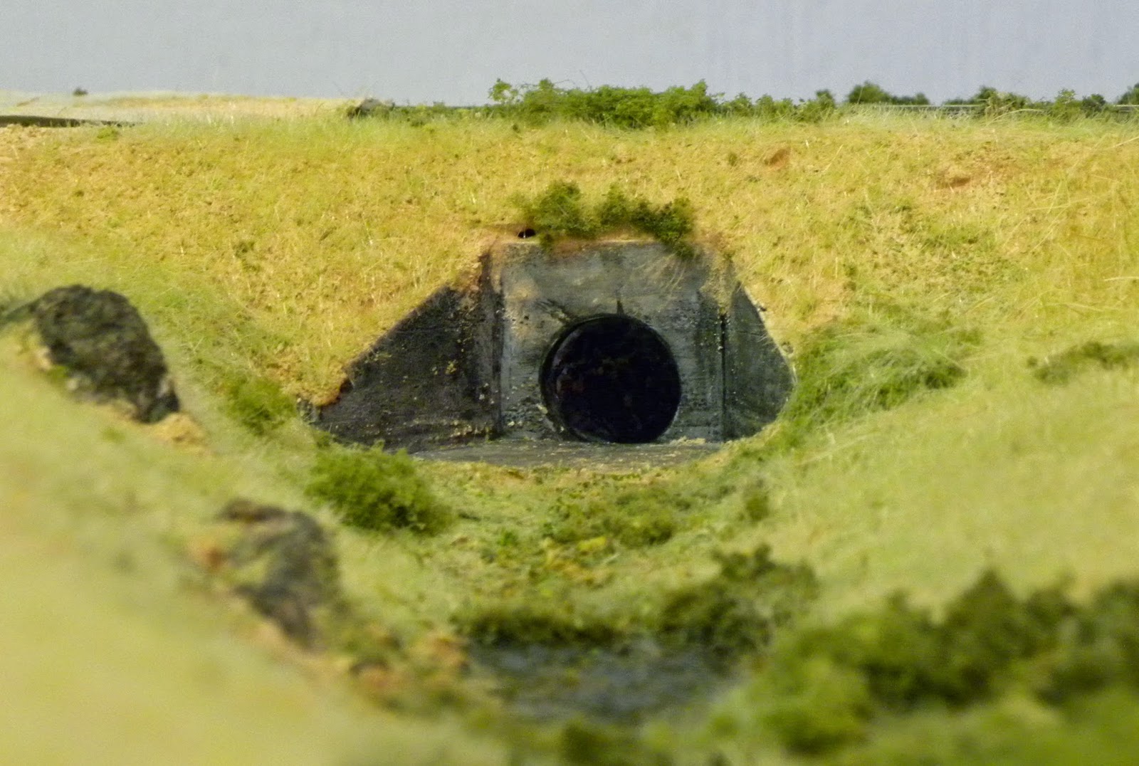
 A 5mm length of the drinking straw was inserted in each opening. After a grey primer coat, the headwalls were given several washes using soft pastels and Isocol
Rubbing Alcohol. The inside of each opening was painted black as was the Styrofoam behind the culvert headwall.
A 5mm length of the drinking straw was inserted in each opening. After a grey primer coat, the headwalls were given several washes using soft pastels and Isocol
Rubbing Alcohol. The inside of each opening was painted black as was the Styrofoam behind the culvert headwall.The photo opposite shows the headwall installed but with grasses and foliage yet to be added.
As I said at the start, these are very ordinary and simple structures, but the humble culvert is something that adds to the overall scenic impression that I am seeking to represent.
As a footnote, I have recently become aware of a range of brick culvert headwalls manufactured by Keiran Ryan (http://www.shapeways.com/model/938743/3-foot-brick-culvert-ho-scale-3.html?li=shop-results&materialId=61). These look particularly impressive, representing earlier designs that were used when many of the railway lines were first constructed. The type of headwalls I have shown in this post are reinforced concrete using designs that probably originate in the 1960s. The reinforced concrete solution would have been used to replace the earlier types of headwalls if they failed. That said, I understand that many of the earlier designs are still in place to this day.
No comments:
Post a Comment