Sunday, 22 June 2014

Running Tender First - A Basic Kadee Adaptor

A few weeks ago, I identified a scenario where I should operate a train pulled by 5248 running tender first. The only problem was there was no compatible coupler on the front of the locomotive. Having just repainted the model I did not want to fit a Kadee coupler, so I experimented with an adapter that could link the coupler on the rolling stock with the existing hook coupler on the locomotive. I'm sure this has been done before, but my searching on the internet didn't bring up any suggestions. So it was back to first principles and this post details the outcome of that experimentation.

By way of background, about a year ago, I came across a number of Youtube movies showing steam operations on the NSW railways in the 1960s. One of these showing operations in northern NSW is at  https://www.youtube.com/watch?v=HDVUsaeFKhs&feature=relmfu . While the quality of these videos is well below the standard of current cinematography , they are a great source of contemporary information on the topic.

Recently, in search of information on MHO guards vans, I revisited this video and was surprised by the number of empty coal trains (primarily LCH and CCH wagons) being hauled by a standard goods locomotive running tender first. So the hunt was on to find a way to replicate this.

After a couple of tries, I managed to get a piece of copper wire shaped in such a way that it would fit a loop into the hook on the locomotive and drop two prongs over the rear of the Kadee coupler. As expected, the copper wire was too malleable, so I fashioned a similar piece using brass wire. This has proved to be successful and is now awaiting painting to match the locomotive and wagons.

You will note from the photo that a second piece of wire has been soldered to the device. This performs two functions. The first is to provide a way to stop the adaptor lifting off the Kadee if the locomotive pushes the wagons for any distance (which the adaptor still does to some extent). The second function is to provide a lifting points for a pair of tweezers or pliers to remove the adaptor when it is no longer needed.


This is a device developed for a particular function and requires a bit of fiddling to make it work. In addition, the normal Kadee features, such as automatic uncoupling and recoupling, are lost, but as I uncouple manually, this is not a problem. Even with the addition wire to retain the adaptor on the hook, pushing forward is done very cautiously. I have also found that it works better with the old Number 5 Kadee rather than the new prototypical couplers but this is probably a matter of further fine tuning.


Notwithstanding these challenges, the device does what is required and now I can haul empty hoppers to Philip's Creek tender first.
 As a  footnote, I had tried to upload a short piece of video to show the adaptor in operation but the process seemed to freeze, so I had to make do without it. The file may have been too large.


Thursday, 22 May 2014

Back Conversion - the consequence of being a pedant

I have always been something of  a pedant when it comes to things historic and I am usually frustrated about the inaccurate portrayal of history or equipment that was not in use during the events depicted. However, in my younger days, I was a bit more relaxed about such inconsistencies in the rolling stock used on Philip's Creek, but as I am getting older, and possibly acquiring a bit more knowledge,  the pedantry is becoming pronounced.

Although I broadened my modelling time period to about six years to allow me to run a greater range of locomotives through Philip's Creek, I have set the end of the steam in NSW as the right hand boundary of my interest. As a consequence , I recently found myself 'hoisted on my own petard' and had to address the issue of rolling stock that was not in service in the late 60s/early 70s.

Over the last few years, I have been gradually upgrading my Powerline and Lima passenger coaches. Interiors were added several years early, but recently, I have been concentrating on external elements, specifically, roof detail and hand rails. The last wagon to be upgraded was a Powerline KB Parcel Van shown opposite. Although I was aware that these KBs had been modified from surplus MHO guards vans, some preliminary research determined that the conversions occurred in the early 1970s, possibly around 1973-74. I decided that it was better to give myself some certainty and so the KB van should be returned to its earlier form as a MHO guards van. And, if I have got my understanding of the timings incorrect, I have just added a MHO to the fleet at the expense of a KB parcel van.

The conversion itself was not difficult, with the roof treatment again using masking tape to simulate the malthoid strips and new torpedo vents fitted once the strips had been set in place. As an aside, I have tried both techniques suggested in recent AMRM articles, teabags and masking tape, as a means of creating the malthoid roof. I think teabags provide a marginally better surface but the masking tape strips are much easier to apply. I also apply a thin film of PVA glue to the finished roof to help seal the work. The photo opposite shows the body as well as the roof before the addition of the torpedo vents.

I purchased an Ian Lindsay under-body kit and used some left over MHG doors and louvre panels for the guard's doors and the coffin/animal compartments. To date, the van has been painted, and weathering to the chassis and roof has also been completed. I am waiting to purchase suitable decals possibly at the Thornleigh exhibition, if not before.

The final photo is a similar but updated version of the first, now with the newly converted MHO immediately behind the 48. The changes only seem minor from this distance, but at least now, it can pass a steam locomotive at Philip's Creek without incurring the frustration of this pedant.


Thursday, 8 May 2014

Hiding Surface Mounted Switches - a couple of ideas

Sometimes we find it necessary to locate items  that support the operation of our model railways on the layout rather than below where most of the wiring, switches and other infrastructure are placed. I choose to operate most of my points manually and, as a consequence, have found it convenient to place a change of polarity switch on the surface adjacent to each point.

The photo opposite shows two switches that were installed last August/September when I replaced some old Atlas points with two Peco electrofrogs. Astute readers will note that this particular photo shows that these points are electrically operated. The reason for this was detailed in a comment to my post in September 2013(http://philipscreek.blogspot.com.au/2013/09/buses-will-replace-trains.html) but the focus of this post is the subsequent work that I have recently completed to conceal those switches.

Not surprisingly, I have found that the easiest way to hide the switches was to incorporate them into the surrounding land form. Of the six switches installed to date, three have been concealed by the terrain adjacent to the track. A small rise or a cutting has been sufficient to achieve the desired effect. The photo opposite shows the start of the branch line on the module currently under construction. I have included a small mirror in the photo to show the switch, partially obscured by masking tape, in its cavern underneath the nearside cutting wall.

By the way, I haven't got around to mowing my static grass as yet. It's hard enough getting motivated to cut the real thing.

Clearly, the use of terrain is most easily achieved on new construction but in situations where the scenery has already been completed, the solutions tend to rely on structures and lineside details. To date, two switches have been hidden under a pile of sleepers and a mound of sand covered by a tarp at Philip's Creek Station. Another has been concealed by a small coaling stage at Mount Windeatt. In each situation, it is necessary to make sure that there is some roof or cover over the switch to ensure it can still operate. Don't forget that in the worst case, one may need to access the switch, so it's prudent to keep the feature as simple as possible.

Basically, I have tried to utilise items of lineside infrastructure that are appropriate for the location, can be placed near enough to the track to conceal the switch, but do not create an obstruction to traffic. For example the mound of sand was used to avoid interfering with passing trains. Other options could include platforms, loading banks, piles of rubbish, fettler's water tanks on a stand or some thick lineside vegetation. I'm sure there are many others.

The final photo links to the first photo showing the area of last September's work but now with the two switches concealed.


Thursday, 24 April 2014

Bringing a Jumbo into service


For someone who proports  to model the NSW prototype in the late 1960s and early 1970s, there is a distinctly non prototypical balance in the relative quantities of  my steam and diesel fleets. The quantity of steam locomotives, while not large, is significantly greater than the number of diesels. Hardly the situation that existed in the dying days of steam in NSW! One could say that this reflects where the heart is but in reality, I also have a soft spot for some of  the early diesels, particularly the Alcos that were in service during my modelling time period.

Until recently, the diesel fleet consisted of just one 44 class and two 48 class diesels. However, this year, I am hoping to redress the balance with the purchase of an Auscision Model 45 class, ordered earlier this year, and the Trainorama 48 class that was ordered back in 2008. However, the first step in this expansion program occurred recently with the purchase of the recently rereleased Austrains 442 class locomotive. For non NSW readers, these were given the nickname Jumbo, because, according to Wikipedia, "their 1971 delivery coinciding with that of Qantas' first Boeing 747". It is a big locomotive in comparison to the 44 class and I suppose it's a similar to the 747s being so much larger than anything else then in service. 

The 442 comes fitted with an 8 pin plug to facilitate DCC connection. The fitting of a basic TCS decoder was achieved without difficulty and then it was time for programming before the unit entered service. Not so, there was a short circuit as soon as the locomotive hit the programming track !! At first I suspected the decoder but Ian at Hobbyland Hornsby, where I purchased the locomotive, showed me that the plug had been wired incorrectly. He corrected the problem with a minimum of fuss. Thanks Ian

For something straight out of the box, this should not have happened. Apparently the problem was not confined to the individual model that I purchased.

Introduced between 1971 and 1973, the Jumbos straddle the extreme right of my modelling period. I understand that my locomotive 44222 was completed in March 1972 and probably entered service shortly afterwards. Therefore, any appearance on Philip's Creek must show a locomotive in an almost new condition, and, as such, weathering has been kept to a minimum. 44222 received light sprays of Humbrol rust wash around the chassis, a coat of clear matt to remove the shine on the body and a little soot on the roof.

I appreciate that there are enhancements that could be made to this model but they can wait for a while. Now that it is in service, the locomotive runs well although its operation has been impeded by frequent line closures to facilitate landscaping activities on the new module. There are also a few places where tolerances and clearances need to be fine-tuned.


Now, I just need to complete the acquisition program. There's a good chance that the 45 class will arrive and maybe, just maybe, the 48 class will finally get here.

Friday, 4 April 2014

Culverts

There is nothing more ordinary than a culvert! They have to be the most ubiquitous means of water or gap crossing for both the road and rail but most of the time, they are completely unnoticed by people who cross them.

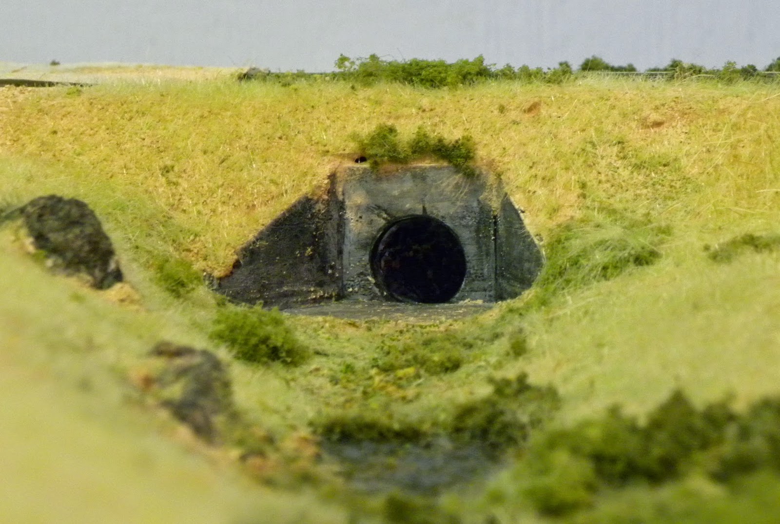
Over the last few weeks, I have been installing two culverts as part of the undulating terrain on the new module. While the siting of these structures is fairly obvious, there is one real life design feature that should be reflected in any model of a culvert. I am speaking about the need for sufficient cover of  earth over the top of the pipe. The compacted material above the culvert spreads the loads on the pipe and prevents crushing. In my earlier working life, the normal rule was that the minimum cover should be the greater of 600mm or half of the pipe diameter. While this metric related to metal or Armco culverts under roads, the concepts are similar. Speaking to a mate still working in the track maintenance industry, he suggests that with the current train loads, the minimum cover requirement may be greater. However, I suggest that for the purposes of railway modelling, the cover over culvert must look substantial.

The first culvert to be installed (a single barrel) was an old Woodland Scenics plaster kit. I had originally intended to install it on Philip's Creek. However, I subsequently found an older style headwall reminiscent of the type used on the Northern Line near Normanhurst where I grew up. So the Woodland Scenics  kit stayed unused till now.

For the second culvert, I wanted to model a broader less well defined creek, and so decided to use a multi barrel arrangement. This had to be scratch built.

I was able locate a drinking straw that measured about 450mm or 18" in HO scale so this became the diameter of my multi barrel culvert. Personally, in 1:1 scale, I would not use a culvert diameter below 600mm as there is too great a potential for blockage. However, in 1:87, this provides an opportunity for a cameo scene with a maintenance team working to clear the culvert.


The headwalls were constructed from styrene sheet using typical dimensions found on page 42 of the Rocla Product Guide (http://www.rocla.com.au/ProductGuide/)

A 5mm length of the drinking straw was inserted in each opening. After a grey primer coat, the headwalls were given several washes using soft pastels and  Isocol Rubbing Alcohol. The inside of each opening was painted black as was the Styrofoam behind the culvert headwall.

The photo opposite shows the headwall installed but with grasses and foliage yet to be added.

As I said at the start, these are very ordinary and simple structures, but the humble culvert is something that adds to the overall scenic impression that I am seeking to represent.

As a footnote, I have recently become aware of a range of brick culvert headwalls manufactured by Keiran Ryan (http://www.shapeways.com/model/938743/3-foot-brick-culvert-ho-scale-3.html?li=shop-results&materialId=61). These look particularly impressive, representing earlier designs that were used when many of the railway lines were first constructed. The type of headwalls I have shown in this post are reinforced concrete using designs that probably originate in the 1960s. The reinforced concrete solution would have been used to replace the earlier types of headwalls if they failed. That said, I understand that many of the earlier designs are still in place to this day.


Thursday, 20 March 2014

Terraforming aka "making a mess"

Just before Christmas, I posted a short summary of the first significant expansion of Philip's Creek for about eight years (http://philipscreek.blogspot.com.au/2013/12/moving-forward-at-last.html). Since then, the track has been laid and, over the past few weeks, I have started to work on the terrain adjacent to the line.

As it has been quite a while since I last did some serious landscaping, it was time to relearn some old techniques and try a few new ones. However, one thing that remains constant is the use of Styrofoam both as a base for the track and a landscaping medium. I have used it successfully for every module of Philip's Creek. It has proved to be stable, lightweight, and, when managed properly, has stood the test of numerous moves without any damage. In my experience to date, there are only two things to be wary of when using Styrofoam, any exposure to petrochemical products which can see your creation disappear before one's eyes, and the mess as the final landform is created. Of these, the first can easily be avoided or managed, the second cannot.

My general approach to building the landforms is fairly conventional, build up layers of Styrofoam, carve them to a final level, apply some form of coating to the Styrofoam and then add various scatter material to finish. The adjacent photo provides an overview of the progress to date.

I mentioned the impossibility to avoid making a mess as the Styrofoam is shaped. My objective has been to contain this mess to the immediate area of the construction and avoid, like the plague, any activity that sees the Styrofoam pellets migrating into the house and the consequent wrath of  'higher authorities'. At one stage, I had two battery power vacuum cleaners working in tandem, with a normal vacuum cleaner as backup.

In shaping the Styrofoam, I have preferred to shave it with a large knife rather than hot wire. I then used the hand rasp shown the photo to achieve the final shape. While it gives a great outcome, it is the tool that creates the greatest mess and requires regular cleaning.

Previously once the shape had been finalised, I either coated it with a coat of plaster or paper towels impregnated with plaster. However, over time, I found instances of flaking or lamination. This time, I decided to try absorbent wipes sprayed with a 50/50 mix of PVA and water and allowed to cure. They are very inexpensive, a pack of 10 cost about $1 from Woolworths. To date, the results have been very positive and the wipes, after the glue has dried, provide a firm hard shell.


I use a mix of earth coloured tile grouts to provide the basic ground cover. This was sprinkled onto good coating of the PVA/water mix and allowed to set. A second coating of the PVA/water was applied just to make sure everything was glued down. One of the unexpected benefits of this was that it highlighted low points in the creek line. The still drying glue can be seen as the white shape at the rear of the adjacent photo. These will become stagnant ponds in an otherwise dry creek line. The preliminary painting for these started, and since the photo was taken, a couple of layers of clear vanish have been added. This was time to be cautious about the interplay between Styrofoam and mineral based paints. Fortunately, no adverse effects have been noted and I suspect that the earlier work has provided an effective seal.

 However, there is still a lot more landscaping to do and the other new technique for me is the use of static grass. I have recently invested in an applicator together with a few different coloured grasses. There appears to be a lot of instructional material available on You Tube and other places but there is no replacement for personal experience, so a few more lessons to learn.


Wednesday, 26 February 2014

The AndIan Turret Tender - Now in Service

My AndIan Turret Tender has now entered service behind a freshly painted and renumbered 50 class.


My earlier post on the tender (http://philipscreek.blogspot.com.au/2014/01/the-andian-5000-gallon-turret-tender.html) showed the model when most of the basic construction had been completed. A more detailed construction sequence is being posted by Peter Hearsum at http://burrowa.wordpress.com/ as he undertakes a similar project.

Thanks also to AndIan Models for providing some spare ladder sides that allowed me to have a second attempt at the ladder.


Painting was fairly straight forward. Because the locomotive was a metal DJH kit, I was able to strip the existing paint using an acetone based nail polish remover. For plastic kits, I have found the non acetone products work well with less risk of damage to the plastic. It took a few attempts but most of the the surface was back to bare metal. The locomotive and tender were both sprayed with a Floquil weathered black and then a light coat of  Humbrol rust wash. Most of the weathering was completed with an airbrush but some rust powder was used in a few additional places.


All of the tender wheels were fitted with phosphor bronze wipers and a permanent electrical connection has been made to the locomotive. I had intended to fit additional pickups to the locomotive but the chassis configuration seemed to make this difficult with the materials I had to hand. A project for another day!

As an aside, I found it necessary to fit a long shank coupler to prevent buffer lock on some of my tighter curves.


Now, what to do with the old tender? In the short term, I'll probably de-coal it and leave it on a siding. However, if in the long term, I manage to purchase a C30T, it may again be pressed into service.