Work on scenery for the Kingston Plains module continues and as the shape of the basic topography is now settled, the module has taken a distinctly blue hue as the absorbent towelling has been glued in place. As an aside, the inspirational photo taped to the back drop was taken
from Ian Dunn's article, 'Moving the Golden Grain', in the April 2006
issue of AMRM. It shows a great view of the Merriwa branch line
terminus in 1970.
As I mentioned in an earlier post, Terraforming - aka making a mess , the next step will be to apply a slurry of the coloured tile grout mixed with of 50/50 PVA/water. Most modellers have their own favourite technique for this stage and I'm
no different. My experience has been that the slurry, once cured,
provides a robust pre-coloured base upon which to add other scenery
elements. Over time, I have settled on a Davco tile grout product that I can source from my local Bunnings mixing a light brown (ten parts of item number 27 or 28) with a Red brown (one part of item number 38).[Update Jan 18 - a recent visit to Bunnings indicates that Davco have changed their coding and colour range. Some experimentation will be required but the mix of a light brown and red brown should work]
The two flanking photos show the view from either end of the module. The wheat silo will be located where the glue bottle is standing and should be the dominant scenic feature for Kingston Plains.
It's a bit hard to believe that Christmas 2017 is rapidly approaching, but it is and consequently, this will be my final post for 2017. If I've been extra good enough this year, an elderly ALCO may find its way onto the Philip's Creek locomotive roster in 2018. Then again, even a lump of coal might be useful as it could be crushed and used to fill the coaling stage at Kingston Plains.
More importantly however at this time of the year, I would like to acknowledge
those individuals who
have assisted me with
comments, advice and information, all of which have enhanced my
modelling activities in 2017.
And finally, to all readers, best wishes to you and your family for a very Merry Christmas and a very happy 2018.
Tuesday, 19 December 2017
Tuesday, 5 December 2017
The Station at Kingston Plains
After getting distracted over the last few months, I had to have a strong talk with myself about focus and priorities. As a consequence of this motivational monologue, I have finally started the landscaping on what is probably the final module for Philip's Creek; that is a branch line terminus now referred to as the fictitious location of Kingston Plains. Work has progressed steadily on what will be a relatively flat landscape.
As an aside, there has been a slight change in the work flow from my past endeavours. Previously, I have shaped the landforms, applied basic ground covers and then progressively added buildings as they they were constructed or purchased. The area around the new building was then resceniced if necessary. However, as I had already been acquiring buildings for this module over several years, my approach now has changed. This time, I have 'planted' several of the major buildings into their final location once the basic 'terraforming' has been completed but before any ground cover has been added. There are risks to this approach as small items of detail could be damaged as the various ground covers are applied, so extra care will be required, but it allows me to adjust the ground cover as necessary to align with the adjacent structures,
The first building in the long running acquisition program was an A5 station building constructed from a LJ Models card kit. (Two articles in Branchline Modeller Number 2 provides additional information on the prototype and extra construction tips) The kit was originally assembled around 2006 with the intention of using it on the Mount Windeatt branch but it did not seem to fit in that location and was put aside for use elsewhere. As Kingston Plains is 'the end of the line', so to speak, it was now or never.The model was recovered from its temporary storage, dusted off and some additional detail such as water tanks and chimneys added.
It was then time to construct the platform. As always, external space constraints come into play and and with a scale platform length of only 40m, it is considerably shorter that equivalent prototypes such as Merriwa. However, as the only passenger service for this line is a single CPH, hopefully, it probably won't look too out of place
The platform was cut from a suitable piece of styrofoam and shaped to suit the track alignment. I had contemplated purchasing commercial timber platform edging but decided instead to fabricate it using materials already to hand.
The wood planking was from a Wills Material Pack (OO instead of HO scale but difficult to pick the difference). The capping timber came from some scrap balsa wood.
Weathering was the usual mix of of white, grey and black acrylics supplemented with a few pastels.
The gravel or decomposed granite platform surface is simulated using a paste, DecoArt Stonelike Textural Acrylics. It took two coats to get sufficient coverage.
The last two photos show the station now fixed in place. Other details such as lights, seating and signage will be added later. Ballasting and other landscaping, when completed, will also hide a multitude of sins but I'm will have to be bloody careful of those finials!
Friday, 3 November 2017
Distractions
Currently for Philip's Creek, the primary objective is to finish the basic scenery for the newly named Kingston Plains branch line. Two posts ago, I wrote about completing the scenery on the Hall's Creek Bridge module which forms part of this branch line, but work on the scenery at the terminus has not started.
The last three to four months have seen a number of activities distracting me from that objective. The most significant of these was a two month holiday, but even before that, other events conspired to impede. A few months ago, my wife showed me one of those articles that frequently circulate on Facebook. This one described how a person got up one morning with the good intentions to achieve a number of tasks but quickly became distracted from the first task, then got distracted from the previous distraction. And so it continued for the whole day until by the end of the day, the person had achieved nothing but felt exhausted by all of the day's activities.
My story was similar and it began when 3123 stalled on a short section of track which bridges the Mount Windeatt branch line modules. Ok, so I'll remove the piece of track, clean it up and replace the joiners. However, as I started this, I accidentally pulled up a longer length of rail. Bugger, but not a problem, I'll replace the damaged section of track and improve the alignment as it was always causing problems for 3123. But to do that, I need to remove the unpainted backdrop that separates the Mount Windeatt station from the unsceniced Muswellbrook staging area. Ok, so while I have the backdrop off the layout, I may as well attempt to paint it to match it up with the section my wife painted a few years ago. But wait, while I'm relaying track near that staging area, I may as well do something to address the chronic overcrowding which can occur. The only realistic way to achieve this was to construct a shelf that will hold surplus rolling stock until these are required. Consequently, by the end of this deductive process, I was left with a number of major projects, none of which contributed to the achievement of my primary objective.
The realignment and replacement of the damaged track was simple, but for someone of my very limited artistic skills, the backdrop painting was a bit more challenging. I chose to use pastels as I was not confident in my ability to merge or blend paint on the backdrop to ensure a good transition of colours. The photo opposite shows the right hand side of the backdrop over the newly realigned length of track. The photo below shows the left hand part of the backdrop back in position.
Increasing the size of staging area was a bit more complicated. The challenge was to provide supports for the upper shelf without restricting the width of the passage way or the space available within the staging areas. I decided to use threaded rod mounted on the frame supports. This also provided a means to ensure that the shelf was level.
So at the end of this period of fairly intense activity, the three tasks
have been completed and then it was time to head off on the
holiday. But still, I was no closer to achieving the primary objective.
And I
wonder why it has taken me 20 years to get this far!
Thursday, 10 August 2017
Track Cleaner v3.0
Well, it's the end of my Woodland Scenics' 'Tidy Track' cleaner. Just under five years ago, I wrote the first of three posts about this tool. Two and half year years later, the shaft broke (http://philipscreek.blogspot.com.au/2015/10/it-broke.html ) and I fitted a sleeve that allowed it to continue to function. However, normal usage over the next two years saw the pivot point gradually break up, get repaired and break again until it finally disintegrated last week. The concept of the tool was good but, clearly, it was not sufficiently robust for my track cleaning techniques.
Fortunately, a few months ago, I had stumbled across two YouTube segments on Ken Patterson's 'What's Neat' column for last January and February. Both discussed how build a similar tool using a standard half inch drive breaker bar. The links to these are:
The breaker bar was purchased from Auto One for around $20 and each base took around an hour to fabricate excluding curing time for glues. Noting that 'Tidy Track' retails for something between $60-$70, it probably represents a significantly cheaper option.
One thing was evident as soon as the tool was put into use. The weight of the bar made the tool considerably heavier than its commercial equivalent and negated the need for the additional force that I had felt was necessary for the effective use of the Woodland Scenics tool.
Ken's February column also noted the impact of the height of the breaker bar's pivot point and the potential to trip up the cleaning head. My experience reinforced this observation. The higher the pivot point above the track, the longer the lever arm and the greater the potential that a minor defect in the track will cause a snag in the movement of the cleaning head.
And so, after nearly five years of adaptions, tweaks and repairs, hopefully, now I have a solution that will work reliably without disintegrating periodically.
To close on a very different subject, readers might like to rewind Ken's January video back to the 2:30 minute mark. Here we see an impressive model of a Northern Pacific Challenger steaming majestically through a nicely timbered scene. However, it is not the locomotive that catches one's attention but rather, his moggy lurking among the trees as this image from the video shows. At the risk of a very poor pun, a very different scenery challenge!
Fortunately, a few months ago, I had stumbled across two YouTube segments on Ken Patterson's 'What's Neat' column for last January and February. Both discussed how build a similar tool using a standard half inch drive breaker bar. The links to these are:
- January 2017 (https://www.youtube.com/watch?v=zNAkczzwQu4&t=164s starts at 2:59)
- February 2017(https://www.youtube.com/watch?v=QuE22ZCqlRw&t=234s starts at 1:41)
The breaker bar was purchased from Auto One for around $20 and each base took around an hour to fabricate excluding curing time for glues. Noting that 'Tidy Track' retails for something between $60-$70, it probably represents a significantly cheaper option.
One thing was evident as soon as the tool was put into use. The weight of the bar made the tool considerably heavier than its commercial equivalent and negated the need for the additional force that I had felt was necessary for the effective use of the Woodland Scenics tool.
Ken's February column also noted the impact of the height of the breaker bar's pivot point and the potential to trip up the cleaning head. My experience reinforced this observation. The higher the pivot point above the track, the longer the lever arm and the greater the potential that a minor defect in the track will cause a snag in the movement of the cleaning head.
And so, after nearly five years of adaptions, tweaks and repairs, hopefully, now I have a solution that will work reliably without disintegrating periodically.
Tuesday, 18 July 2017
Halls Creek Bridge 4
Never let it be said that progress on Philip's Creek moves at any speed other than ultra dead slow!
It's now just under three years since the most recent article dealing with the completion of my model of the Hall's Creek bridge (The Halls Creek bridge 3 - still work in progress). Since that time, very gradually, scenery construction has moved forward as these 'before and after' photos show.
The styrofoam was glued in place, shaped and a surface fabricated using the same techniques as those described in my earlier post (Terraforming-aka making a mess).
The creek was made using fairly common modelling techniques. A good overview of these is at https://www.youtube.com/watch?v=dug-ffEhqZU&t=1375s . To simulate the water, I used a gloss Bondall Clear Timber Varnish taking care to ensure that no unsealed styrofoam came into contact with the varnish, lest it created an unexpectedly deep sinkhole. The general ground cover was a mix of new grass and straw static grasses.
I also experimented with static grass clumps and strips and probably went a bit overboard with this. Initially, I wanted to create a green fringe along the edge of the creek and I needed to provide some grass coverage of the ground underneath the bridge. Some of these didn't work out as I had hoped with the clumps under the bridge creating a rougher surface than the surrounding ground. Course foam was used in an attempt to mitigate this.
Ultimately, this 1.8m section of of the layout is intended to add some sense of distance to the branch line, and the basic scenic treatment supports this intent. It also provides the opportunity to replicate photographs such as this great one from the Rail Transport Museum Calendar 1992 June (photographer understood to be Graham Cotterall). But for that to happen, it needs a manufacturer to finally decide to model the 30T!!
Thursday, 8 June 2017
Getting the Roof Right
At the recent Modelling the Railways of NSW Conference, I
purchased a 4 wheeled lourve van kit from Casula Hobbies. This particular kit
was a model of the longer 11ft 6in wheel base version of the LV coded wagons. A
few years ago, I had purchased an IDR 10ft wheel base van and the difference
between the two versions can be seen in this photo of a wagon from the Oberon
Tarana Heritage Railway website
(http://othr.com.au/rolling-stock/goods-wagons/
photographer unknown) shows the longer wheel base van sitting on top of
a 10ft chassis.
Conceptually, both kits are the same, a cast body and a
separate chassis. Details such as handrails can be added to the model. The main
difference between the kits was that the Casula kit has a separate CGI roof. I
understand that some wagons had the CGI removed but I elected to construct the
van with the separate CGI roof. The
Casula kit included two CGI roofs from the GSV that needed to be cut to size,
joined and then fixed to the body. My problem with this arrangement was that
the battens were in the wrong locations and whole arrangement seemed too thick.
I decided to create the roof from a commercial CGI product
but the main challenge was to determine how this would be fitted to the van
body. My research uncovered a few images that led me to deduce that the roof
was supported by a number of ribs supporting the CGI sheet sandwiched between
thing battens. I fashioned several strips of styrene to match this and fixed
the roof to these.
The photos below show a side and end images of the van. The
side image appears to be to be a reasonable representation of the prototype and
compares reasonably with the IDR model of the10ft version. The photo from the
end also seemed to match other photos from the same angle which I had found.
So, thinking it was completed, I started the painting with
the usual coat of primer. Concurrently,
I also started to put together a few thoughts for this post. As I went
searching for the Oberon Heritage Railway site to get the reference correct, I
located a few of Keiran Ryan's photos (http://www.krmodels.com.au/topic01.html
). These clearly showed that I had misinterpreted the support arrangements for
the roof with independent brackets used to support the CGI and supporting
battens. While the image from the side still seemed to work, the ends should
show the individual supports rather than a continuous rib that I had
built. With a few choice words that
cannot be printed, the roof came off, the outside ribs were removed and
replaced with individual supports under the battens. The final version before
painting is shown below.
Fortunately, I was able to correct this error but it makes
me wonder how many others have fallen through the cracked. Probably quite a few
I suspect!
Postscript. It never rails but it pours! During a visit to the great Epping Model Railway Club exhibition at Thornleigh on the weekend, I purchased an Austrains LV pack on special, so now I have five of these wagons plus the smaller IDR version.
Sunday, 30 April 2017
A water tank for a K truck
I recently purchased a Roads and Rail Resin water tank, a model of a water tank designed to be fitted onto a KF flat wagon or into a modified K truck. The manufacturer indicates that the model can be fitted to either an Austrains or IDF KF wagon or use the sides included in the kit to adapt a KF wagon into a modified K wagon.( Road and Resin water tank ). I really wanted to build a modified k truck version and didn't want to sacrifice my only KF wagon (an IDR KF wagon) for that purpose.
When I first saw an add for this kit, I purchased a Casula Hobbies K truck hoping it could be used in lieu. Unfortunately, there is some dimensional variations that meant that the tank was too big to fit inside the Casula version. So I made up the tank to fit onto the KF wagon.
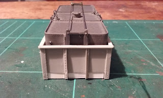
However, with further reflection, I decided that the Casula Hobbies K truck could be adapted. I glued several strips of styrene to increase the size of the base (see photo opposite), fixed the completed tank to the base and then fitted the modified K truck sides around the tank. It was also necessary to adjust the wheel mountings to ensure the correct height above the track.
Painting and weathering will follow but this has been an exercise in dimensional variability as can be seen from the three versions in the photo opposite, an original Casula Hobbies, an original Austrains model and the modified K truck mounted water tank. I suppose as long as I make sure that they don't appear in close proximity to each other, then differences are not too obvious.
Thursday, 16 March 2017
Contract out your fencing
Fences are a fact of life in both urban and rural environments and in my quest to 'model the ordinary', they are certainly a feature that should be included as part of the scenery. Several of my earlier posts have discussed some aspects AND the frustrations of modelling fences.
As I mentioned previously, the tedious nature of the task, particularly when building a standard barb wire fence quickly dents the enthusiasm. Consequently, the task frequently gets put in the 'too hard' or 'lower priority' basket. To overcome this, I decided to call in some extra help and engaged a fencing contractor, Paddy's Fences to finish the task.
While I had been contemplating this solution for a while, it all fell into place when I found some castings of barbed wire coils manufactured by Model Train Buildings (www.modeltrainbuildings.com.au ) at the recent Forestville Exhibition. The figures came from second hand stalls at other exhibitions and the Holden ute was purchased a few years ago.
The contractor's name acknowledges a recent visit to the layout by an eight year old great nephew. While he seemed to enjoy running the trains, he definitely enjoyed playing with the red ute. Paddy's favourite ute became the workhorse for Paddy's Fences.
I haven't recorded the time spent building this little cameo but it is definitely a lot less than would have been expended running and tensioning all of the 'wire' myself!
Subscribe to:
Posts (Atom)