Showing posts with label Singleton. Show all posts

Saturday, 16 December 2023

Hunter River Bridge - Finishing the scene - 1

Following on from my recent post, finally, the scenic work has closed up on the Hunter River. While the work modelling the banks and the littoral areas is fairly routine, modelling the wide expanse of water flowing under the bridge will be a bit more challenging.  

As usual, the landform is foam board, carved and shaped around the bridge abutments. The following photos show the river banks before the final shaping.  These were topped with the domestic wipe disposable towels topped with coloured tile grout and, as usual, there was liberal use of 50/50 PVA glue and water.  My biggest fear while doing this work was accidental damage to the bridge. Fortunately, that didn't happen.

With the banks sorted, I have started to paint the river bed as the first step in the challenging task of adding the actual water. The Google satellite image opposite shows the actual crossing site with the current bridge. As can be seen, the site was located just east of a major bend in the river. With a bit of modeller's licence, I moved the crossing site onto the actual bend so that the transition to the backdrop was easier to achieve. The main river channel is on the outer (northern) side of the bend and there is an accumulation of sediment on the inner (southern) side of the bridge.

In preparation for the final task, I was able to visit Bob at South Coast Rail to see how he had created the water for his excellent model of the Thomson River bridge. ( http://southcoastrail.blogspot.com/ )  I really appreciated the opportunity to understand his technique. Thanks Bob. 

Now, hopefully in the current heatwave, I'll be able to find a day when the temperature in the garage is reasonable enough to tackle this.


And finally, in recognition of the time of the year, Christmas has come around again and this will be my final post for 2023. As the year rapidly draws to a close,  I'd like to take the opportunity to wish all readers a Merry Christmas and a very happy 2024 for you and your family.

Having just crossed the Hunter River bridge, 4473 heads north with a load of empty wheat wagons.


Saturday, 2 September 2023

Inspired by True Events - Building the Albion Hotel at Singleton

"Inspired by true events" is a caption often seen on movie and TV screens of late. Basically, it means that the script writer has adjusted or amended a true story by altering events or adding different characters which to increase the drama and/or romance of the film. I, for one, am often cynical about these alteration, but if I'm honest, I must also recognise that such changes are also the essence of prototypical modelling. And my latest foray into scratch building underscores the concept of prototypical rather than prototype.

In my most recent post, I made reference to the Albion Hotel, a building which is located just north of Singleton railway station on John Street. I presume that this proximity was the prime reasons for its original construction. My research managed to locate a number of hotel surveys, including a few photos, which had been published by the ANU. https://openresearch-repository.anu.edu.au/handle/1885/136613 These show that the Albion appears to have been built well before 1926 but went through a significant number of changes over time, with probably the most significant occurring some time between 1960 and 1981when a major extension was completed on the western side. These changes are apparent in the two photos below.

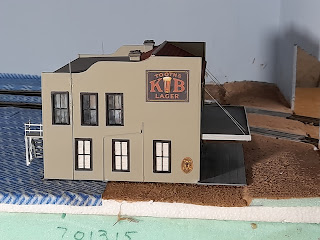
I opted to build the 1960 version and have assumed that the extension was not completed until some time after 1973, the upper limit of my modelling time period. The key features I wanted to capture were the shape of the side walls, the awning, the large KB sign and the tiled roof line at the front.

Unfortunately, as I realised later, the KB sign only appeared on the eastern side as there are windows on the western side. But it's the western side that faces the operator. Oh well, that's an example of when inspiration trumps fact! (No political pun intended)


The model was primarily constructed from styrene with brass wire for downpipes and external plumbing. Doors and windows are Tichy products. The windows are oversized but are what I had to hand at the time. The signage and interiors came from the internet. Unfortunately, the large KB signs are not the exact ones in the 1960s photo but are probably close enough. The chimneys came from a good mate who recently acquired a  3D printer. He has also printed a few other items beyond the scope of this article but they will probably be the subject of a subsequent post. A balcony railing has yet to be fabricated.

The sign on the awning was produced using PowerPoint and incorporates a fictitious name of the licensee. This name, William Clarke, comes from my family history, a maternal great great grandfather. He was a publican in Birmingham around 1890. Incidentally, before that he had spent about 20 years on the footplate as a locomotive driver, although, a family story indicates that he was fired from that job for drunkenness.  Still, he was the obvious choice.


The hotel can't be fixed into its final position until the backdrop and ground cover have been finalised. And not to mention the level crossing, hopefully with sensors activating flashing lights, immediately behind the hotel. But that's a challenge for another day!


Tuesday, 27 September 2022

Hunter River Bridge - final positioning


Well, it's only taken three years but the Hunter River Bridge has now been incorporated into the layout albeit with 'bumper rails' just in case something failed.

It was an easy process to remove temporary structure which has bridged the gap for the past 12 months but I had erred slightly with horizontal alignment, failing to allow for the offset of the track on the bridge. Rectifying that mistake was easy, relocating the bridge about 10mm laterally. The 3mm ply strip which serves as the bridge foundation was screwed to the base board frame.

Once the bridge was in place, I glued the track on top of the trusses with PVA glue using timber off-cuts to hold it in place as the glue cured. I still have to fit  check rails but this will happen when the scenery is completed.

Since the photos were taken, the base board frame has been covered by 3mm ply which, in due course, will become the Hunter River. Gaps have been filled with tape and jointing compound and the 'bumper rails' have gone.


The bridge will be the major scenic feature on the lower level of the layout but as I mentioned in my previous post, scenery will wait until other areas have completed. I'll then face the challenge of creating a wide expanse of water, something I haven't tried before.  So there's still a lot of work to do before I can recreate to the image that started it all ('Northern Exposures' (p 128, photographer Greg Triplett))


Sunday, 21 August 2022

Hunter River Bridge - a bit more work

Just a quick update post on my long running Hunter River rail bridge. In my most recent post on this project at the end of March, I said that I was wrestling with the challenge of how to get a sandstone block finish on the piers and abutments. Eventually, I located a paper product called Art Printers Dressed Stone Building Papers from Modeller's Warehouse. 

The finish looks great but is very delicate. Don't use masking tape to hold it in position. The building papers are supposedly a self adhesive product and it does stick to itself but it is less successful adhering to the foam that was used to construct the abutments and piers. It was a fiddly job particularly working around the curved surfaces and it was necessary to use PVA glue in some instances when the self adhesive failed. White exposed edges were painted with acrylics.

I then used weathering powders in an attempt to represent the aged stone of the prototype. Although it looks OK, it is a much redder than I had hoped. But it is what it is. 

I fitted the three 'steel' trusses with the assistance of a three foot spirit level and then fixed a piece of timber underneath to stiffen the structure until the bridge is installed. (thanks for the suggestion Rob). Once the backdrop has been installed, the bridge will be dropped into position and the track re-laid. Scenery will happen in due course but other areas will take priority.


Tuesday, 29 March 2022

Hunter River Bridge - Piers and abutments.

It seems that several modellers are completing long delayed models. Maybe not completing but my Hunter River bridge model has also seen a bit of recent progress. I had first mentioned its construction in October 2019 but progress has taken a back seat to other tasks associated with moving and reassembling the layout. That post focused upon the construction of the trusses whereas this post concentrates on the construction of the two intermediate piers and two abutments. As I had noted previously, my modeller's licence requires the bridge to be shortened from five spans to three.

Originally, I had contemplated a potential a 3D printed solution but I struggled to develop suitable graphical images. So instead, I reverted to a first principles physical model using shapes cut from a sheet of  XPS Handy Panel foam board. As I mentioned, this product is easily sawn and shaped with little mess. With care, it can even be screwed.

The piers were fitted to a sheet of thin sheet of plywood. When complete, the bridge will replace a temporary section on the layout.

The photos opposite and below show stages of the construction process. A piece of timber, visible in the second photo, was inserted into each column to assist securing it to the ply and provide additional support to each of the trusses. Most of the cutting was completed on a band saw and glued together with PVA glue.

I applied several coats of Uni-Pro Smooth Coat to cover the foam board. This is intended to seal the foam and create a surface in preparation for whichever finish is applied.


I have wrestled with a method to finish the piers and abutments. Ray Love's photo opposite (Ray Love 'Days of Steam', p67) appears to shows the piers and abutment constructed out of sandstone blocks. At this stage, I anticipate applying a suitable printed paper product unless other solution emerges. 


The photo below, a reprise from my January post, shows the bridge sitting on the track above its final location. Once the support structure has been finished, I'll fit the trusses and track before lowering it into position.  But now, it's still a work in progress but as I said earlier, nothing happens quickly at Philip's Creek!


Monday, 7 October 2019

Singleton Hunter River Bridge

Despite the closing comments in my last post ( Contingency Planning ), I have started work on a model of the Hunter River rail bridge near Singleton. How this model will be integrated into Philip's Creek has yet to be seen and, probably in the short term, it will remain as an independent diorama and possibly be used as a separate DCC programming track.  

The current bridge is the third in that location. Ray Love in his book 'Days of Steam' provides a brief description of the three iterations. These are also shown in the montage opposite found on the internet (https://www.researchgate.net/figure/The-Hunter-River-at-the-Singleton-rail-bridge-in-a-1861-b-1866-c-1963-and-d_fig4_48381152) The first bridge, a five-span laminated timber structure (Images (a) and (b)) was built in 1866. It was replaced in 1902 by a five-span riveted steel Pratt truss structure (Image (c)). In turn, this bridge was replaced when the line was duplicated with a steel girder structure (Image (d)). I'm not sure when the duplication took place but I understand that it was well after my modelling time period of the late 1960s, early 1970s. Consequently, the 1902 Pratt truss version is the subject of my modelling effort. Since the post was first published, Col Hussey provided some additional information on the 1902 version which can be found in the comments section below.


My research to date for this project has been restricted. Life has got in the way preventing a visit to the Australian Railway Historical Society so I have relied on two photos, extracts of which have been reproduced below. The first photo showing a 60 class hauling a load of LCH/CCH wagons is from 'Northern Exposures' (p 128, photographer Greg Triplett).


The second showing a 36 class leading the Brisbane Express over the bridge is from Ray Love's book 'Days of Steam' (p67, photographer Ray Love). Ray's photo, in addition to showing detail on the truss arrangement and weathering, also gives a good indication of how the original piers were modified to accommodate the 1902 bridge.


I used these photos to estimate key truss dimensions by comparing the bridge elements with the equivalent HO scale locomotives.These were used to create a template for the fabrication of first two trusses. Each truss was built using styrene only with the major components of each truss using various  profiles all around 3.2mm wide. Cross bracing was a combination of angles and flat sections.


These two trusses will form one span of the bridge and have been used to develop construction techniques. They were also used to test  each span's load carrying capacity.  .

The following three photos show the construction sequence  The internal bracing was the most difficult to fabricate. I only fitted one of these every second bay and I can't determine from the photos whether that spacing is correct. However, the lateral bracing of the top chord is the most critical to resist the bending failure of the truss and this was easy to fit.


The final stage to confirm the viability of trusses was the load test. In something reminiscent of the famous load test of the Sydney Harbour Bridge albeit with significantly less potential consequences of failure, I used 6018, as the heaviest load the bridge will carry, to test the capacity of the span. It passed! A slight vertical deflection was noted but I don't think this will have any significant impact on the functionality of the bridge. Incidentally, I understand that the actual bridge was restricted to a single 60 class, so it's probably close to the mark.


I want this bridge to fit onto a single 1800mm module but  with each span measuring around 340mm plus the substantial abutments and approaches, a five span bridge will be too long. It's probably time to apply some modeller's licence and reduce the number of spans from five to three. But more of that later. In the meantime, it's time to build more trusses.